1 Optical Fiber Bending Loss With Stress Effect
Mechanical bending of an optical fiber induces a refractive-index gradient via the photoelastic effect, modifying bend loss predictions. This article demonstrates two equivalent approaches for modeling this stress effect within the SMF-28 fiber using OptiMode’s FEM solver: (i) explicitly incorporating the stress-induced index tilt, and (ii) replacing the physical bend radius with a stress-corrected effective radius. Simulations across bend radii of 6–13 mm confirm that both methods yield identical bending loss results.
2 Theory
Bending a silica fiber produces mechanical strains that modify the glass index through the photoelastic effect. In the weak-guidance limit (i.e., the index contrast between the core and cladding is small) and this appears as a linear index across the bend as follows [1]
\[\begin{equation} n_{\text{stress}} = n(x,y) + \Delta n \;\approx\; n(x,y)\!\left[\,1 - \frac{n^{2}(x,y)\,x}{2R}\,\underbrace{\bigl(P_{12} - \nu\,(P_{11}+P_{12})\bigr)}_{photoelastic\ term}\right] \end{equation}\]
where \(n(x,y)\) is the unstressed index, \(P_{11}\) / \(P_{12}\) are silica’s photoelastic coefficients, \(\nu\) is Poisson’s ratio, R is the bending radius, and x is the coordinate across the bend. For a typical silica fiber (\(P_{11}=0.116\), \(P_{12}=0.255\), and \(\nu=0.174\)) the photoelastic term is positive, which results in \(\Delta n\) being negative on the outer side of the bend and positive on the inner side, i.e., the index decreases outward and increases inward.
Equivalently, the stress-induced index can be modeled as a modification of the bend to an effective bend radius [1]
\[\begin{equation} R_{\mathrm{eff}} = \frac{R}{\,1 - \frac{n^{2}}{2}\,\bigl[P_{12}-\nu\,(P_{11}+P_{12})\bigr]\,} \end{equation}\]
For the above parameters and \(n=1.44346\) at \(\lambda=1.55\ \mu m\), this gieves \(R_{eff}=1.2475R\). This larger effective radius reduces bend loss in standard silica fibers. Here, two equivalent approaches are considered: (i) simulating bend loss with the stress-induced index tilt explicitly included, and (ii) simulating bend loss with the effective bend radius in the conformal solution.
3 Design
The simulation of the optical fiber with stress effect is performed using the finite-element method (FEM) solver in OptiMode at an operating wavelength \(\lambda = 1550\ nm\). The general solver settings for the FEM solver are those used in the optical fiber bending loss article. The implementation of (1) is achieved by evaluating the stress-induced refractive index using a python script and exporting it to a text file. This refractive index file is then imported to OptiMode using the “add user file” functionality. Figure 1 shows the refractive index distribution in OptiMode assuming the stress effect.

| Bending radius (\(mm\)) | Equivalent \(R_{eff}\) |
|---|---|
| 6 | 7.48 |
| 7 | 8.73 |
| 8 | 9.98 |
| 9 | 11.22 |
| 10 | 12.47 |
| 11 | 13.722 |
| 12 | 14.97 |
| 13 | 16.21 |
The implemenation of (2) is achieved using the conformal mapping bend functionality of the FEM solver, see [optical fiber bending loss]{Optical_Fiber_Bending_Loss}, but using the \(R_{eff}\) corresponding to the desired \(R\). Table 1 shows \(R_{eff}\) values for bending radii ranging from \(6\ mm\) to \(13\ mm\).
4 Results
Figure 2 compares macrobending loss predictions from the two approaches—(i) explicit stress-induced index using (1) and (ii) a stress-free model but using the effective radius \(R_{eff}\) from (2) across bend radii of 6–13 mm. As can be seen, there is a good overlap between the two curves, confirming the equivalence of both approaches for this model of the SMF-28 fiber.
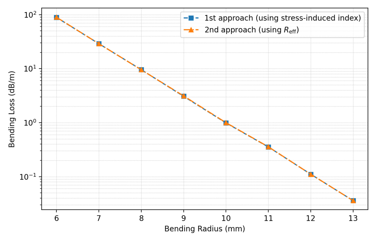
The agreement between the two methods confirms that, for standard step-index silica fiber, the stress effect does not need to be modeled explicitly — replacing the physical bend radius with \(R_{eff}\) is sufficient and considerably simpler to set up. The explicit stress modified refractive index approach remains useful when the fiber geometry or material departs from the silica parameters assumed here (e.g., non-silica glass, heavily doped cores, or photonic crystal fibers), where the correction factor would need to be recalculated and the linear-index approximation may no longer hold.