Optical fibers are the primary medium for light transmission in modern communication systems, enabling low-loss signal propagation over long distances. However, when an optical fiber is bent, its performance can degrade due to bending losses. These losses occur because bending distorts the guided mode distribution away from the modes of the straight waveguide, causing part of the optical power to leak from the core into the cladding and eventually radiate out of the fiber.
Understanding and accurately modelling fiber bending loss is crucial for optimizing fiber design, maintaining signal integrity in optical networks, and enabling compact photonic integration where tight bends are often unavoidable.
In this work, we investigate the bending loss characteristics of the standard single-mode fiber (SMF-28), focusing on the dependence of attenuation on the bend radius. The analysis is performed in the macrobending regime, where the bend radius is much greater than the core radius. Numerical simulations are compared with analytical results [1–2] in order to evaluate the consistency of the results between the analytical model and the FEM solver for SMF-28 fibers.
2 Design
The simulation of the optical fiber is performed using the FEM solver found in OptiMode at an operating wavelength \(\lambda = 1550 nm\). The general domain and solver settings for the design are given in Tables 1 and 2 respectively.
Table 1: Domain settings.
Domain Settings
Value
Wafer width (x-axis) (\(\mu\)m)
\(150\)
Wafer thickness (cladding) (\(\mu\)m)
\(80\)
Wafer thickness (substrate) (\(\mu\)m)
\(80\)
Mesh points (x-axis)
\(800\)
Mesh points (y-axis)
\(800\)
Boundary conditions
PML
Table 2: Details of general solver settings in the FEM solver.
General Solver Settings
Value
Minimum angle (degree)
\(10\)
Min Edge Length (\(\mu\)m)
\(0.05\)
Max Edge Length (\(\mu\)m)
\(0.3\)
Max Triangle Area (\(\mu m^{2}\))
\(0.5\)
Element Order
\(2\)
The SMF-28 is modelled as a doped-silica core (\(n = 1.44916\)) surrounded by pure-silica cladding (\(n = 1.44346\)) [2]. The structure is approximated as a core (\(8.3\ \mu m\) diameter) surrounded by an infinite cladding (\(70–80\ \mu m\) from origin with PML boundary conditions). This approximation is physically justified as the \(62.5 \mu m\) thick cladding is sufficiently large compared with the \(4.15\ \mu m\) core radius and the effective mode diameter. Fields sufficiently distant from the core will experience losses from the PML, allowing for bending loss calculations.
Simulations of bent waveguides can result in non-physical interference states between the domain and boundary conditions. To ensure guided modes are found, modelling starts with simulations set to a large bend radius (e.g. \(1\times10^6\)\(\mu\)m); for this case, mode index estimate is set to use max index. The simulation is configured to return up to \(30\) modes, and the modal indices for the well-confined modes are noted. The bend is then “walked” to the desired radius in steps with the modal index from the previous run used as the mode index estimate for the next, ensuring that the solver follows the same mode branch. These simulations can be repeated with a sweep of bend radii to study the bending loss characteristics.
3 Results
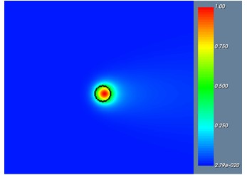
As the fiber is curved, the modal field is no longer symmetrically confined within the core and begins to shift toward the cladding. This is shown in Figure 1, which presents the \(|E_x|\) distribution when \(R = 6\ mm\). This distortion of the fundamental mode results in radiation leakage, which is captured as an imaginary component of the effective index.
Figure 1: Amplitude distribution of the \(E_{x}\) component in the bent optical fiber with R=6 mm.
The bending loss in dB/m can be extracted from the simulated results using the imaginary part of the effective modal index in the following equation:
\[\begin{equation}
Bending\ Loss (\mathrm{dB/m}) = 4.343\left[\frac{4\pi\,Im\left(n_{\mathrm{eff}}\right)}{\lambda}\right]
\end{equation}\]
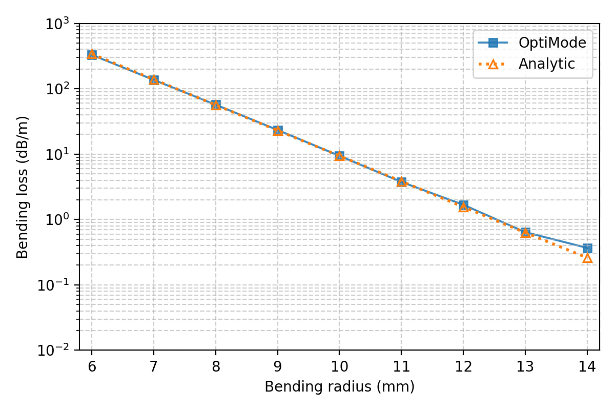
As expected, increasing the bend (smaller bend radius) results in further deformation of the mode and increased radiation loss as the mode field extends further into the cladding. Figure 2 shows both the simulation results and those calculated analytically [1]. Losses below \(0.5\ dB/m\) at \(R = 14\ mm\) rise to hundreds of dB/m at \(R = 6\ mm\). The simulation results show excellent agreement with the analytical model.
Figure 2: Bending loss of the fundamental mode as a function of bend radius, comparing OptiMode simulations and the analytical model.
References:
L. Faustini and G. Martini, “Bend loss in single-mode fibers.” Journal of Lightwave Technology, vol. 15, no. 4, pp. 671–679, 1997.
J. Van Erps, C. Debaes, T. Nasilowski, J. Watté, J. Wojcik, and H. Thienpont, “Design and tolerance analysis of a low bending loss hole-assisted fiber using statistical design methodology.” Optics Express, vol. 16, no. 7, pp. 5061-5074, 2008.