1 Distributed Bragg Reflector
A Distributed Bragg Reflector (DBR), also known as a dielectric mirror, is a critical optical structure designed to provide high reflectivity at specific wavelengths through the interference of light in multilayered materials. This structure consists of alternating layers of materials with different refractive indices, with each layer’s thickness chosen to satisfy the quarter-wavelength condition. The result is constructive interference at a particular wavelength, leading to strong reflection. DBRs are widely used in applications such as laser cavities, optical filters, and wavelength-specific mirrors.
This article explores the DBR design proposed in [1], highlighting the role the number of periods plays in achieving high-performance DBRs.
2 Design
In [1], the proposed DBR is composed of Silicon Nitride (\(SiN_{x}\)) and Silica (\(SiO_{2}\)) materials with contrasting refractive indices operating at a freespace design wavelength of \(\lambda_D\) = 550 nm, see Fig. 1. Silicon nitride has a refractive index of approximately \(n_{high}\) = 2.16, while silica has a refractive index of \(n_{low}\) = 1.46. The combination of these materials allows for the creation of a highly efficient reflector at the design wavelength, making this structure suitable for the DBR design.
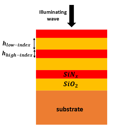
Layer thicknesses are selected to satisfy the quarter wavelength condition, giving the following:
\[\begin{align} h_{\text{high}\mskip 1.5mu \text{index}} &= \frac{\lambda_D}{4 n_{high}} = 63.7\,\text{nm} \\ h_{\text{low}\mskip 1.5mu \text{index}} &= \frac{\lambda_D}{4 n_{low}} = 94.2\,\text{nm} \end{align}\]
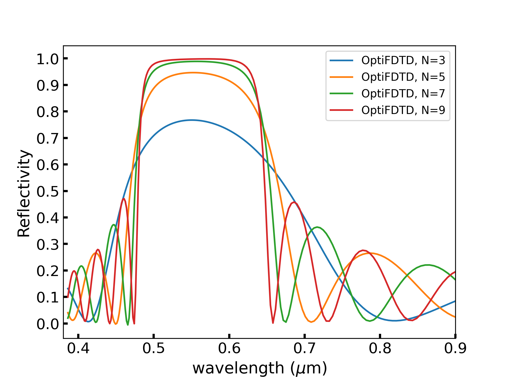
The number of periods (N) (pairs of high- and low-index materials) determines the sharpness of the reflectivity peak, with more periods yielding higher reflectivity and narrower bandwidth. The resulting structure can achieve near-total reflection at \(\lambda_D\), with the reflectivity significantly decreasing at off-design wavelengths.
For normal incidence, the reflection coefficient (R) at \(\lambda_D\) is given by the following formula [2]
\[\begin{equation} R = \left[ \frac{n_{\text{air}}(n_{\text{high}})^{2N} - n_{\text{sub}}(n_{\text{low}})^{2N}}{n_{\text{air}}(n_{\text{high}})^{2N} + n_{\text{sub}}(n_{\text{low}})^{2N}} \right]^2 \end{equation}\]
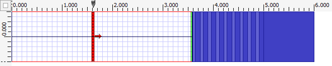
The simulation of the DBR is performed using 2D-finite difference time domain engine within OptiFDTD. The general layout for the simulation of a DBR is shown in Fig. 2. For other settings of the design e.g. dimensions of the simulation region, the boundary conditions and the input plane features see tables 1 and 2. Each layer is created using a linear waveguide set to a channel waveguide profile (WG_channel_example) with the corresponding refractive index.
| Wafer properties | Value |
|---|---|
| Length along x (\(\mu\)m) | 1 |
| Length along z (\(\mu\)m) | 6 |
| Boundary conditions (z = 0 \(\mu\)m and z = 6 \(\mu\)m) | Anisotropic perfectly matched layer (APML) |
| Boundary conditions (x = 0 \(\mu\)m and x = 1 \(\mu\)m) | Periodic boundary condition (PBC) |
The input plane was set up with a rectangular distributed optical source, positioned at z = 1.6 \(\mu\)m.
| Optical source features | Value |
|---|---|
| Wavelength (\(\mu\)m) | 0.55 |
| Half width (\(\mu\)m) | 2 |
| Direction of propagation | z |
| Time domain shape | Sine-Modulated Gaussian Pulse |
| FWHM (sec) | 0.45e-015 |
3 Results
The 2D simulation is performed for the TE polarization (\(E_y\), \(H_x\), and \(H_z\)). The plot in Fig. 3 presents the reflectivity spectra (R = 1-T) of the DBR for varying numbers of periods, i.e. N = 3, 5, 7, and 9. The observation line (detector) is placed at the interface of the DBR and the superstrate (air). Each curve in the plot demonstrates how increasing the periodicity impacts the spectral response of the DBR. The trend indicates that a higher number of periods allows the DBR to achieve nearly perfect reflection over a narrower wavelength range, which is advantageous for applications requiring high spectral precision.